Tuesday, December 23, 2014

2004 Acura TSX 2.4 Engine, Right Rear Door Actuator Replacement


(***This is not a picture of the actual vehicle we worked on. This is a picture of a similar vehicle, a 2004 Acura TSX. This picture is found at: http://images.dealerrevs.com/pictures/64200518.jpg.)

We had a 2004 Acura TSX with a 2.4 engine come into the shop with a customer complaint of inoperative door locks. We were told the vehicle had been purchased from the original owner. The original owner said the door locks all stopped working at the same time.

The customer had already had a couple of parts replaced on the vehicle to try and solve the problem, but the original complaint persisted.

First, we confirmed the customer complaint. We discovered that the LF (i.e. driver's front door) door lock worked properly. It would lock and unlock both with the key in the door and with the switch. (The customer had told us the remote had not worked in a long time, so it was not part of the equation.)

We also noticed the LR (i.e. driver's rear door) would lock intermittently, but would never unlock. We pulled the wiring diagram and tested through the schematic. The fuses all checked good and the circuits were working properly. When we would operate the locks, you could feel the door locks trying to lock and unlock.

We concluded the culprits causing the problem were the individual door lock actuators on the LR, RF and RR doors. The LF worked perfectly.

In this article we will show you the steps to replace the RR door lock actuator. We replaced all three (LR, RF and RR), but will only show the one. The LR is identical and the RF is similar, though there are some slight differences.

In the picture below, you will see the RR door. At this point, nothing has been disassembled.


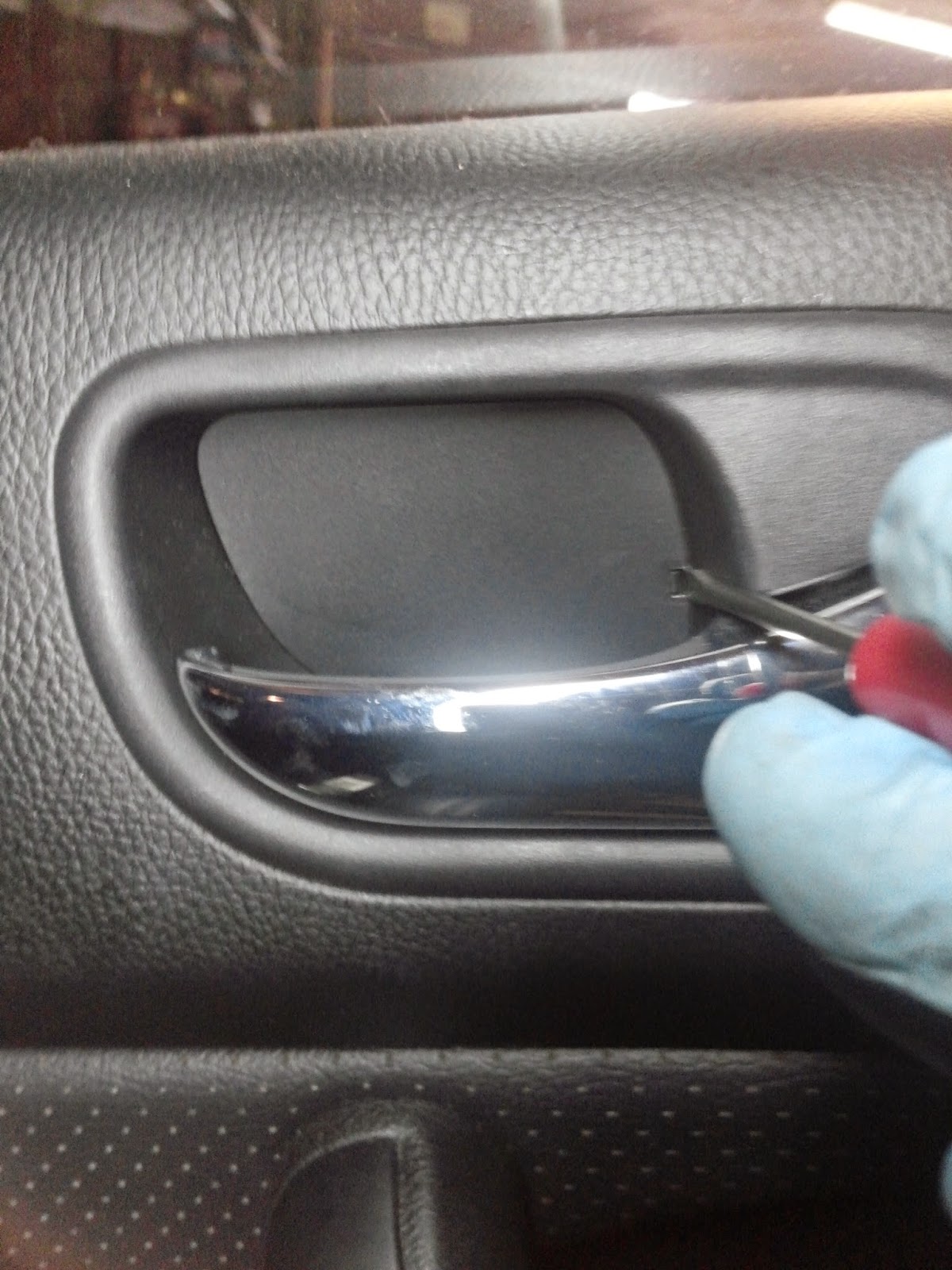
There is no particular order to follow with some of the removal process, this is just how I choose to do it. First, remove the inside door handle cover. There is a small tab that needs to be depressed and then the cover will pull out. I used a pocket screwdriver to depress the tab.


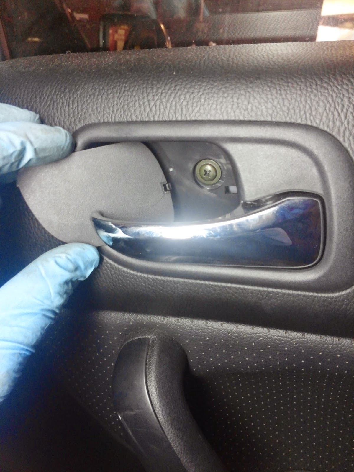
Next, remove the two fasteners (screws) behind the cover.


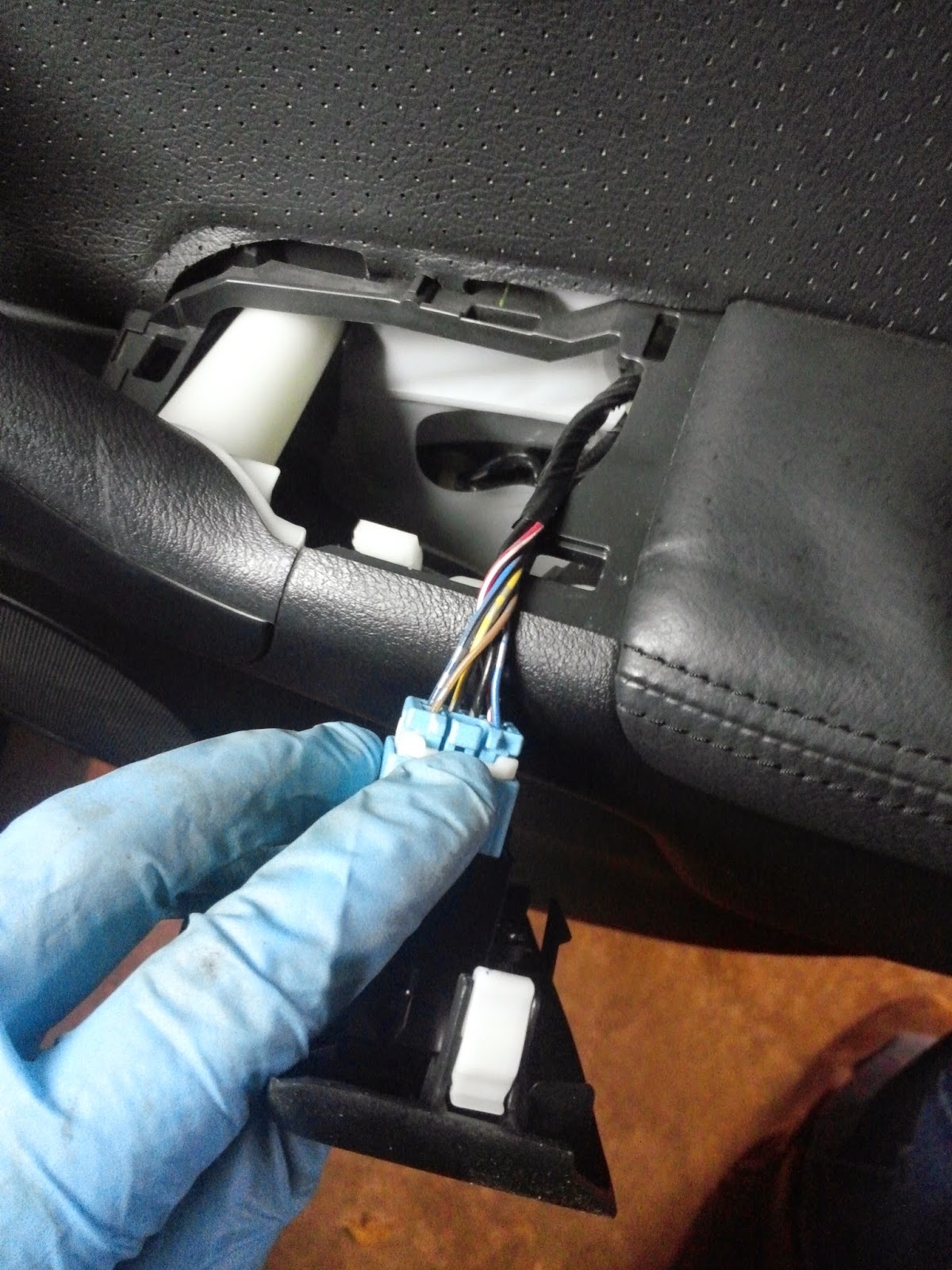
Next, I removed the door window switch. I used a pocket screwdriver to leverage under the plastic and popped it up to remove it from the door handle.


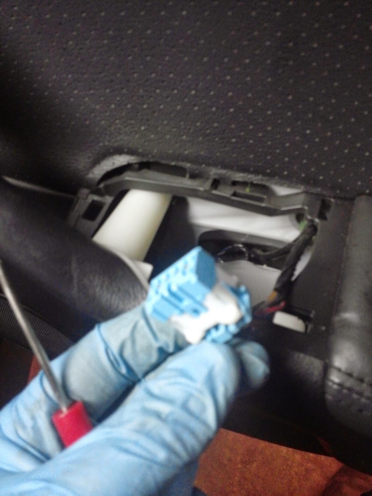
Depress the tab to disconnect the wiring harness from the door window switch.


Next, remove the plastic cover on the door handle. Be careful as not to break the plastic tabs on the cover. Again, the pocket screwdriver was utilized to pop it off.


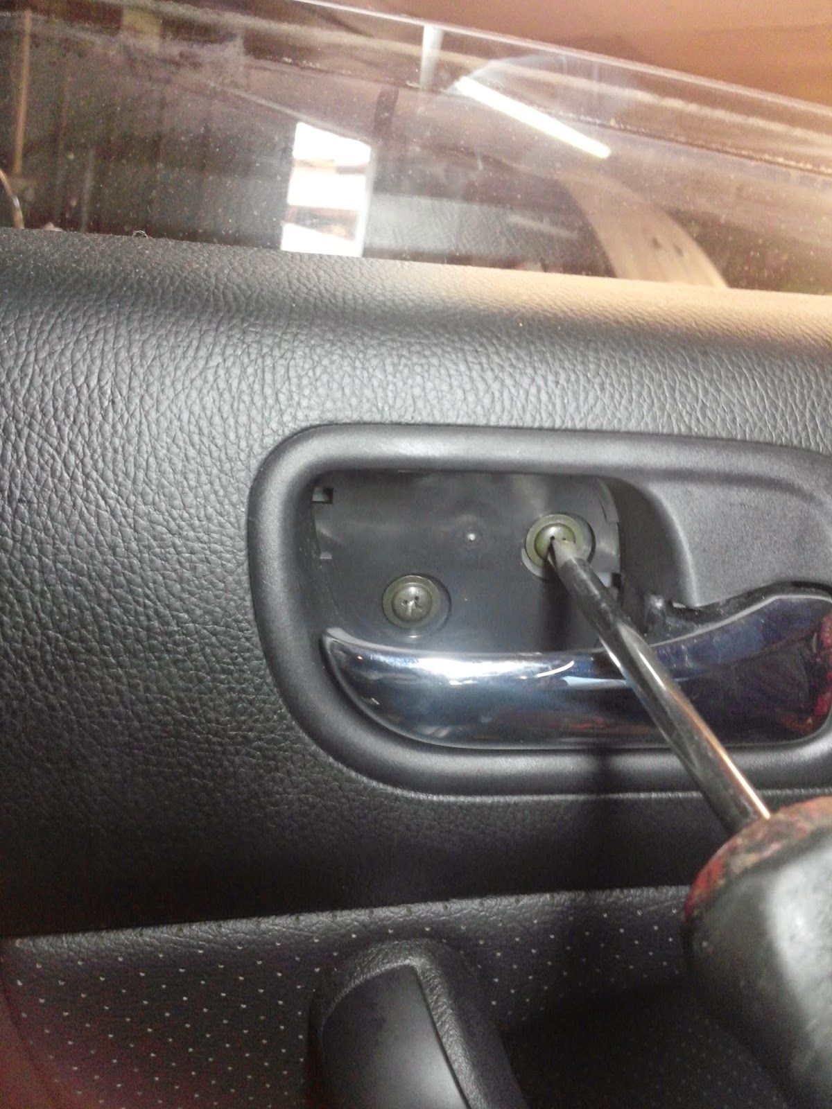
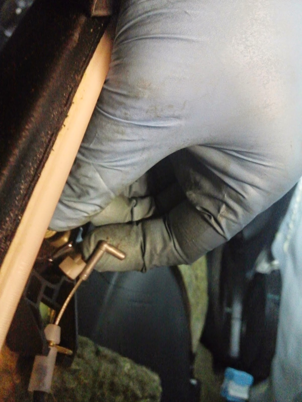
Once it is removed, two bolts can be seen that need to be removed. They are Phillips headed fasteners.


Here is a closer look at the bottom fastener.


Here is a closer look at the upper fastener. Remove each with a Phillips screwdriver.


Next use a tool to pop the door panel keepers away from the door.


Once the door panel is loose, the door handle cable must be detached. There is a plastic keeper that must be pushed back to allow the cable to come out of the inside door handle assembly.

Below, the cable is visible once it has been detached from the inside door handle assembly. At this point, the door panel can be removed from the door and set aside.

Here is a look at the inside of the door with the panel removed.


The plastic must be partially removed (peeled back) to access the door lock actuator assembly. First, use a tool to remove the plastic keeper at the top right corner.


Next, peel the plastic back out of the way.


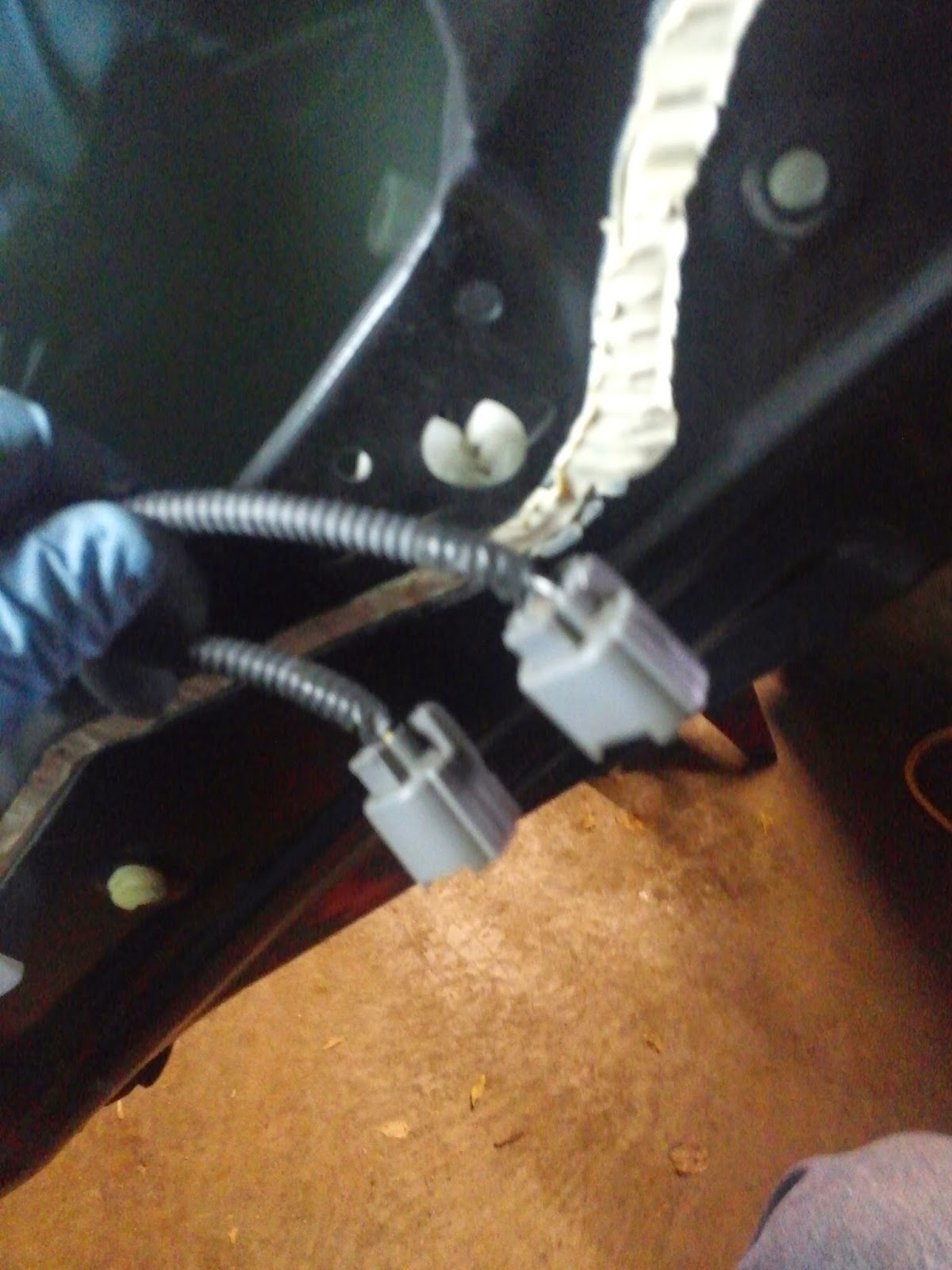
With the plastic pulled back out of the way, the door lock actuator assembly can be seen. Here the two electrical connectors are visible. These must be unplugged.


Below are the two connectors unplugged from the door lock actuator assembly.


The next shot is a bit tough, but inside the door, there is a rod that must be disconnected from the door lock actuator assembly. It is the outer door handle rod. Like the one before (i.e. the inside door handle cable) there is a plastic keeper that must be pushed back to allow the rod to be removed from the assembly. This keeper was brown and is visible in the picture below.


Once the outer door handle rod has been disconnected, the three fasteners (again Phillips) must be removed. These three fasteners are the main ones holding the door lock actuator in place. Be careful! These can be tough to get out and you do not want to strip the heads. If you do, you will have to pull out the drill!


Once the three fasteners have been removed, pop the inside door handle cable keeper off the door.


The door lock actuator assembly will now drop down and pull out of the door.


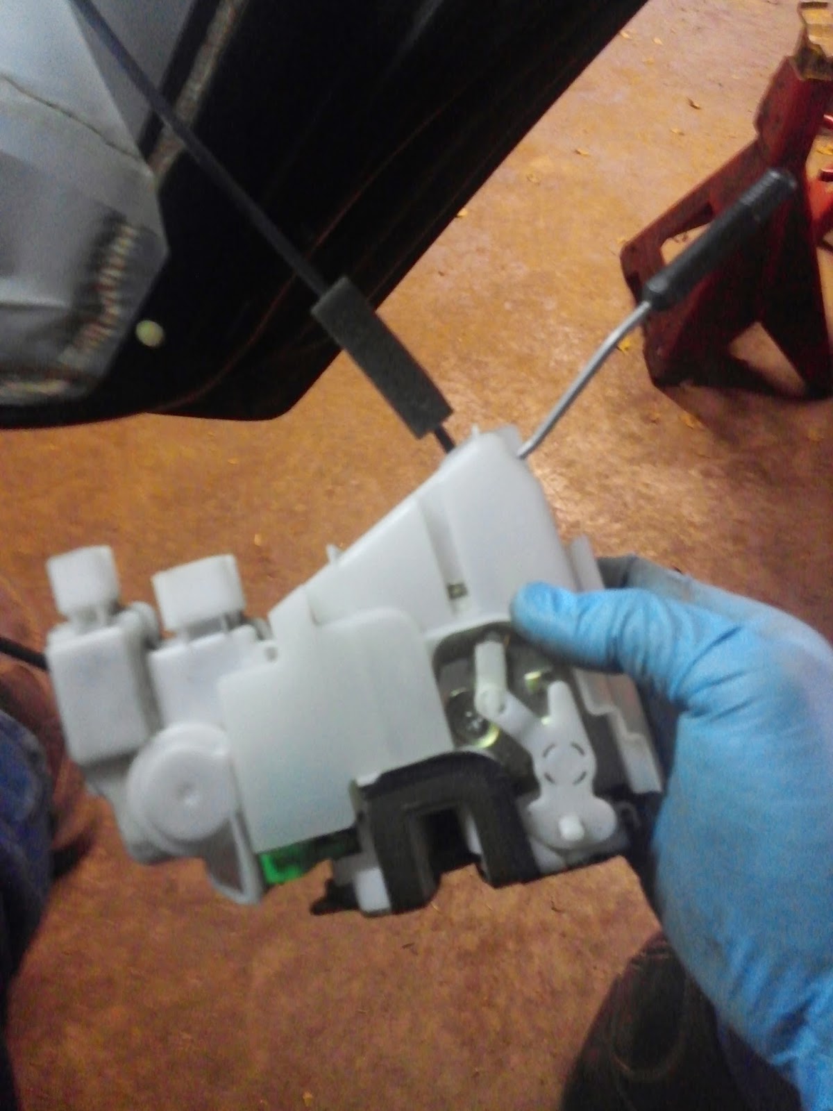
To remove the actuator itself from the assembly, remove the screw holding the plastic cover.


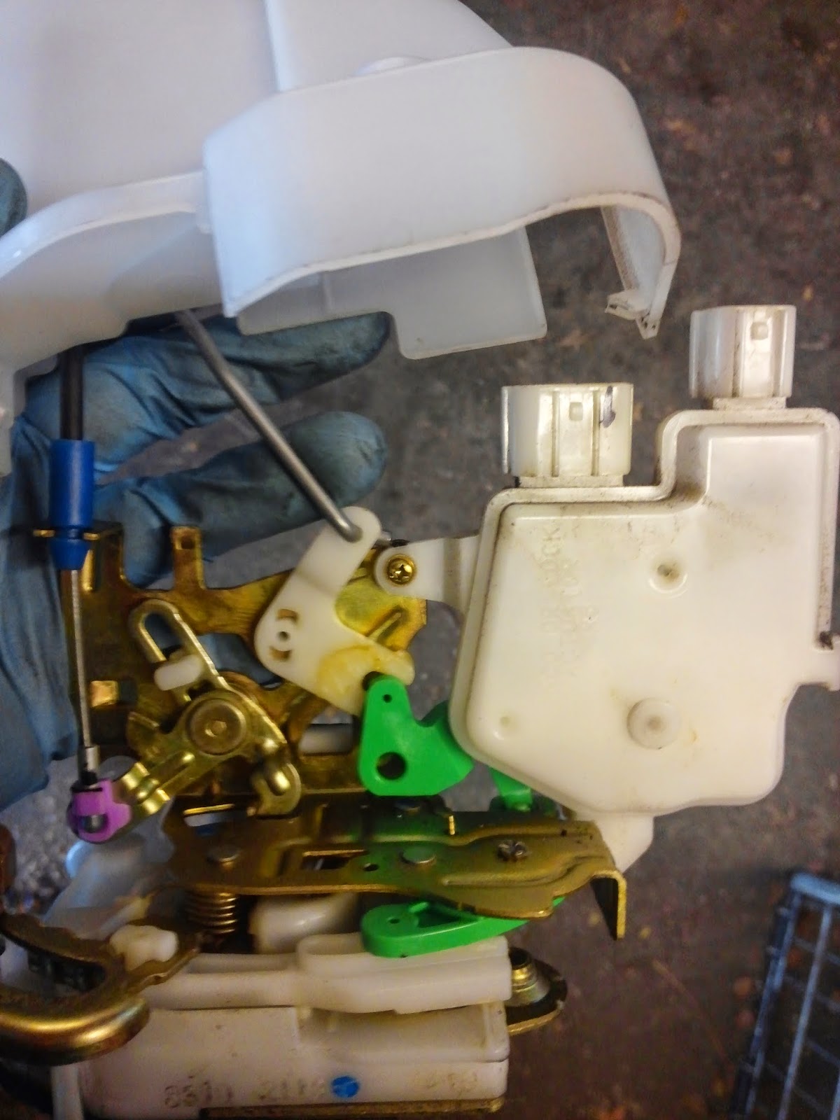
There are a couple of tabs to depress to allow the plastic cover to be pulled back out of the way, so that the door lock actuator is visible.


Remove the screw holding the actuator in place and gently lift the actuator away from the assembly.


To reassemble, just reverse the preceding steps. Once everything is reassembled and the wiring harnesses and door cables and rods are reattached, always test their operation before finishing the job. Make sure the door locks work properly, both locking and unlocking. Make sure the outer and inner door handles will open the door. Make sure the window switch operates the window up and down.

Make sure to leave a clean work area. Use cleaner if necessary to clean the door panel, window and outside of the door.

Once we were done, we tested everything and all was a go. The door locks on all doors now worked properly and normally.

With that, we shipped the vehicle. Another job done.

Wednesday, November 12, 2014

2004 Chevrolet Silverado 4.3, Left Side Marker/Turn Signal Bulb Replacement


(This is not a picture of the actual vehicle we worked on. This is a similar vehicle, a 2004 Silverado. The picture is from: http://www.edmunds.com/chevrolet/silverado-1500/2004/?sub=regular-cab.)


We did an oil service on a 2004 Chevrolet Silverado 4.3. As part of an oil service, we always do a safety inspection on the vehicle. The safety inspection consists of checking things like tire pressure, belts and hoses and the external lights, among other things.

As we checked this one, we found the left side marker/turn signal bulb was not lighting. Many have questions about how to change certain bulbs on vehicles. Some are easier than others. Here is how you change this one. 

First, we had to remove the headlamp assembly. To do this, we had to remove the holding pin. It simply slides out.


Once the pin is removed, the headlamp can be lifted up and moved out of the way. We did not disconnect the headlamp, we just simply moved it aside to gain access to the lower assembly.


Now that the headlamp assembly is moved, we can get to the lower assembly. There is a plastic tab that moved be pressed to snap the assembly out of the bracket, allowing it to be moved to get to the bulb. In the picture below, I am pointing to this plastic tab with my screwdriver.


Once the tab is pressed, gently pull forward on the assembly. Be careful as this is done, so as not to break the plastic tabs. The picture below shows the assembly moved out from the bracket.


Below is another picture of me pointing to this plastic tab, this time with the assembly removed. This gives a better view of the tab.


At this point, it is a matter of replacing the burnt bulb. A simple twist of the connector will free it from the housing, then pull the old bulb out and replace it with a new one. The next picture shows the bulb now illuminated.


We then put the connector back into the housing and snapped the assembly back in place.

When reinstalling the headlamp assembly, you must get the plastic tabs/line up pins in the proper slots. The picture below shows the two tabs on the bottom of the headlamp assembly.


Those two tabs go into two slots. The picture below shows the two slots.


Once these are lined up properly, the headlamp assembly will go back in place and the holding pin can be slid back into place.

Once everything was back together, we did a quick recheck to make sure the bulb was illuminating properly. 

Wednesday, September 3, 2014

2001 GMC Jimmy 4.3, No Power on Acceleration, Fuel Delivery Problem


(This is not the actual vehicle we worked on. We did not get a picture of it, so we are just showing a comparable one. The one pictured is a 1999 GMC Jimmy from http://www.edmunds.com/gmc/jimmy/1999/.)

***This entry will not be so much a "how-to" as it will be a teaching point about testing a fuel pump's circuits before removing it from the tank. Therefore, there will not be as many pics in this post. We will simply discuss what we did and then focus on the test, with a couple of pics to go with it.***

This vehicle came into the shop with a customer concern of no power on acceleration. The customer described the symptoms as bogging when pressing the accelerator. The customer believed the fuel filter could have been the issue.

We drove the vehicle and verified the customer's concern. There was a definite issue with fuel delivery. We checked the readings on the Scan data and found the O2 sensors were reading lean at WOT (i.e. Wide Open Throttle). At WOT, with proper fuel pressure and volume, the O2 sensors should peg out Rich. In this case, they did the opposite, they dropped to 0mv, indicating a fuel delivery issue.

We put a fuel gauge on the vehicle and got a reading of around 50psi. This vehicle's spec is 60psi and up.

We removed the fuel filter first and sure enough, it was completely clogged. Per the customer's request, we changed the filter first and test drove the vehicle again. As we assumed, the vehicle had the same symptoms.

It was now time to drop the tank and take a look at the fuel pump. The filter was an obvious issue. It was stopped up due to a lack of proper maintenance.

The pump probably failed because of the poor shape of the filter. The pump had to pump against that resistance and simply wore out because of it.

One mistake that we have seen committed over and over, is having a faulty fuel pump and then simply jerking it out and putting a new one in the vehicle. There is a simple test that needs to be performed before removing the old pump.

That test is called a voltage drop test. Basically, with this test, the tech is testing the power side circuit and the ground side circuit to make sure everything is good. A problem with either of these circuits can cause the same symptoms a bad pump will display.

If there is a problem in one of the circuits, even though the pump probably will need to be replaced, if the tech simply puts a new pump in the vehicle, it will not be long until that pump is faulty too.

We have seen, and heard, of many such cases where a pump is replaced, only to have the new pump go out within a few weeks or months of installation. The issue, almost every time, was not a faulty new pump (though that does happen); but rather, an issue with the circuitry.

The issue is that resistance builds up in one side of the circuit or other and causes the pump to fail prematurely. If the test is done and too much resistance is found, the tech then has to divide the circuit and start searching for the problem area.

We won't give a detailed definition here of voltage drop, it can be found easily online.

Before removing the original pump, here is the test we performed to check the voltage drop. The picture below is where we back probed at the fuel pump electrical connector.


We took a DVOM meter and connected one end to the battery and  the other to the fuel pump electrical connector. We tested the power side first and then the ground side.

What we were looking for is a reading under about .5v or 500mv. As long as the reading is below half a volt, the circuit is good and the pump can be replaced with no worries. (The test must be performed with the pump running.)

First we test the power side. In the picture below you will see the reading is well below 500mv.


This test told us our power feed was good. We then moved to the ground side. As you see in the picture below, it too was below the 500mv threshold.


This test took 5-10 minutes. In that short time, we tested and found the power feed and the ground circuits to be in good electrical shape.

We were then confident to R&R the original pump, retest the pressure, take it for a test drive and ship it to the customer.

Taking the time to do the little things right, will help to prevent costly and unwanted returns. It makes the tech's life simpler and happier and the customer's too!

Wednesday, July 16, 2014

2006 GMC Sierra, 5.3, 4WD, Rear Brake Shoes (Single Spring Application)


This 2006 GMC Sierra 5.3, 4WD, came into the shop for its 100,000 mile maintenance. We replaced the spark plugs, wires and air cleaner element. We also added oil to the front and rear differentials.

Another service we performed was an all-around brake job. We replaced the front brake pads and the rear brake shoes. We also had the front rotors and rear drums resurfaced at a machine shop.

In this post, I will concentrate on the rear brake shoes. These have a single spring application. They are known to be a bit of a problem. Many techs and DIYers complain about this setup. I will show you a few things I have learned from doing them.

In the two pictures below, you will see the single spring. It looks something like a horseshoe and has a lot of pressure on it. They do make a special tool just for pulling this spring back and removing the brake shoes. I did not use the tool on this job. It is possible to do the job without the expense of the special tool. However, caution is advised, as the spring is very tight.


In the picture below, you will see one of the brake shoes. On this application, the whole apparatus is replaced. When you purchase the new brake shoes, it will come with the shoe and the parking brake lever attached. All of it comes off and is replaced, unlike on other applications where you simply remove a keeper and the parking brake lever remains on the vehicle. 


Removing the cable from inside the spring going to the parking brake lever can be troublesome. In the picture below, you will see the new brake shoe (parking brake lever and spring conduit attached). The parking brake cable goes through the spring conduit and hooks to the parking brake lever. Again, this is the part that many people find very frustrating.


To make this much easier here is what I do: first, (on this model with extended cab), I look below the back of the extended cab on the frame. In that area is the connector for the front cable coming from the parking brake to the two rear cables each going to one side respectively. Below you will see the area and then a picture of the connector on the frame:


Once the connector is located, I detach one (or you can do both at the same time) of the rear cables. See the picture below:


I can actually detach it just using my hands, so it is not that hard to do. I believe the top cable goes to the right (passenger) side and the bottom one goes to the left (driver) side. Once the rear cable is detached from the connector, I now have slack on the other end (the brake shoe end) to move the cable in and out easier. See the picture below:


There is a tab on the end of the spring conduit that must be pressed down to allow the cable to slip out of the spring. Sometimes the cable will come out of its own accord once I detach the connector. Now the brake shoe (with parking brake lever) will slide right off the parking brake cable. See the pictures below:


To remove the shoes themselves (without the special tool) I simply use a large screwdriver, pliers and a pair of side-cutters. There is an adjusting spring to remove, along with the adjuster.


I always grease the contact points to make for a nice, smooth and quiet braking experience. I use caliper grease on the rear brakes and front as well. See the picture below:


I also make sure to clean up all hardware with a good quality brake cleaner.


Once the job is done, I always torque the lug nuts to specification.


I torqued all four wheels to spec and then test drove the vehicle. All was well. The brakes felt good and smooth and the parking brake worked smoothly as well. We shipped this one to the customer. Another one fixed.